Force Probe Collision (Lab 8 - Part 1)
Parts needed :
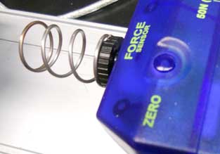
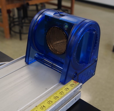
- 2 Force Probes with springs (shown below)
- 2 Motion sensors (not shown)
- 2 USBLink (not shown)
- 1 track
- 2 500-gram bar mass (to make one cart "heavier")
- 2 magnetic carts
- 2 L-shaped plexiglass
Force Probe Collision (Part 1)
The force probe should start with the spring already attached - since we don't calibrate the force probes - no need to change that!
"Area under the curve" for one of the runs
Make sure "AREA" is set under the "summation" menu. (You could unselect the Minimum, but leave the Maximum selected).
Select one of the "force bunches" (try not to go too far along the ends - stay with the main bunch.
Try to make the second area in the same time range!
This shows the other force graph being measured - try to line up the ends of this "click and drag" to match the previous time range (the yellow edged section in the above image).
Note: in this example - the areas don't match up too well - the force probes might not have been calibrated properly - your numbers should be closer than these.
A trick: If you are looking for the upper area - start your cursor below the time axis and drag upward and over. When you go to do the lower area (change to that data run in the legend) - start ABOVE the time axis and drag down and over ... this way you can start and stop the dragging so that they are lined up with the other area.
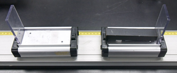
Mounting the motion sensors (part 2 and 3)
Mount a motion sensor at each end of track as shown.
Parts 2-3 - Which velocities should be positive and which negative?
Suggestion: figure out which motion sensor will read POSITIVE if the cart is going away from it .. then use that as the primary motion sensor (and out from that = positive). That sets up a coordinate axis for your track (you might want to write that on a piece of paper/tape near that sensor to remind you!).
We start with a moving mass .. call that mass1 .. that will have a positive initial velocity. IF it bounces back, it will have a negative velocity (and that will be read by the initial motion sensor properly as negative (see the blue comments in the picture to the right).
The second mass (mass2) will be stationary when we start and after the collision it will ALWAYS start moving in the original direction of the first mass ... but the motion sensor for this cart will read that value as negative ... BUT, in our coordinate system, we want that to be positive .. so take the absolute value of the recording from the second motion sensor .. since those velocities should always be "positive" (according to our coordinate system), but will be read by the motion sensor as negative.
In summary - the primary motion sensor (near the starting mass) always will read the velocities with the correct signs (and we should record those correct signs). .. The "other" motion sensor will always read negative, but we want to record those answers as positive.
In addition - the diagram to the right indicates "good" areas where you would select the appropriate data graphs to read the three velocity values discussed above - close to the collision, but in reasonably constant regions of the data run.